Seals have a crucial influence on the system’s performance. The life and reliability of what is often considered a simple component can make a difference to your products and operations.
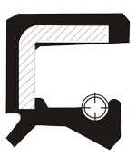
Radial shaft seals are elements that seal the inside of the medium on rotating machine parts and prevent the ingress of impurities from the atmospheric outer environment.
The surface between the sealing edge and the shaft is the most important. The sealing effect is achieved by pre-loading the sealing lip, making its internal diameter slightly smaller than the shaft diameter. The garter spring provides constant mechanical pressure and maintains the radial force to the shaft, flattening the sealing edge to defined width. Sealing is the result of the surface tension of the hydrodynamic oil layer between the seal flattened area and the shaft. Oil thickness must be between 1 and 3 micro millimeters as to avoid leakage. The meniscus acts as an interface between the outside air and the fluid. Any break in the meniscus will result in leakage. This can happen if the shaft contains scratches along the seal path.
The metal insert or case is used to give the seal strength and rigidity. It is usually made of cold rolled steel in accordance with the standard DIN 1624. Stainless steel can be used to avoid rust or chemical corrosion attack. Chromium-Nickel AISI 304 (DIN 1.4301 - V4A), Chromium-Nickel Molybdenum AISI 316 (DIN 1.4401 - V4A).
The garter spring maintains the radial force exerted by the sealing lip around the shaft surface. It is usually made of SAE 1074 spring harmonic steel wire (DIN 17223) or AISI 302 chromium nickel stainless steel wire (DIN 1.4300).
The shaft hardness and surface finish are of prime importance for achieving a useful lifetime. Basically, the hardness should increase along with the increase in peripheral velocity. According to DIN 3760, minimum hardness required is 45 HRC. At a peripheral speed of 4 m/s, the hardness should be 55 HRC and at 10 m/s it should be 60 HRC. In case that the shaft is not fully hardened, the recommended hardness depth is 0.3 mm. Lubrication is also very important. Surface treatment according to DIN 37600 should be Ra 0.2 to 0.8μm, Rz 1 to 5μm, with Rmax 6.3µm. Rougher surfaces generate higher friction, and therefore higher temperatures. Machining defects and scratches on the shaft must be avoided. Even the slightest defects can be sufficient to increase layer thickness, eventually damaging the meniscus and causing leakage. It is also important to avoid spiral grinding or marks, as they may result in pumping effect and leakage. Recommended mechanical processing tolerance is ISO h11 according to DIN 3760 (see table).
Shaft diameter |
Tolerance |
|
|---|---|---|
od |
do |
h11 |
6 | 10 |
0 |
10 | 18 |
0 |
18 | 30 |
0 |
30 | 50 |
0 |
50 | 80 |
0 |
80 | 120 |
0 |
120 | 180 |
0 |
189 | 250 |
0 |
250 | 315 |
0 |
310 | 400 |
0 |
Permissible speeds in a pressure-free state according to DIN 3760
Sealing lip temperature is the mean temperature increased by the temperature caused by the friction heat. The higher the effective working temperature, the faster the aging of the elastomer will be, thus affecting the performance of the sealing lip and the shaft. Friction heat depends on the design and the material of the seal, peripheral speed, sealing lip preloading spring force, the design of the shaft and surface finish, lubrication, medium, etc.
In practice, there is little or no differential pressure. When the rotary shaft seal is exposed to pressure, the sealing lip is pressed against the shaft, thereby increasing the temperature. In some cases, the pressure may cause overturning of the sealing lip.
At higher peripheral speed and pressure above 0.2 bars, or at a lower peripheral speed and pressure of 0.5 bars, spare rings or specially designed rotary shaft seals with a stronger sealing lip and supporting metal insert must be used. For lower speeds, we recommend our PP types. However, permissible overpressure with PP-type shaft seals is limited (see diagram).
On request, we can provide shaft seals with special reinforced lip to withstand pressure over the indicated value. If spare rings are installed, standard shaft seals may also be used. However, spare rings increase the cost, and often the space required for their installation is not available. Sometimes the use of spare rings is not even possible since it requires a very precise fitting as well as very low shaft eccentricity
For this reason, rotary shaft seals (PP-type) are a better solution, even if more accurate fitting and lower shaft eccentricity are required than in usual cases.
Rotary shaft seal permissible overpressure.
Our rotary shaft seals are manufactured according to DIN 3760 and Quality Assurance Standards ISO 9001: 2001, ISO SRPS 9001: 2008 and ISO SRPS 9001: 2015.
All production phases are checked and all measurements are recorded and stored for eventual data verification. Interference allowance and permissible eccentricity
In accordance with DIN 3760.
Seal outer diameter d2 |
Interference allowance(1) |
Tolerance on |
||
|---|---|---|---|---|
preko |
do 80 |
Type |
Type |
Type |
over 50 |
to 80 |
+0,30 |
+0,23 |
0,25 |
over 50 |
to 80 |
+0,35 |
+0,25 |
0,35 |
over 80 |
to 120 |
+0,35 |
+0,28 |
0,35 |
over 120 |
to 180 |
+0,45 |
+0,28 |
0,35 |
over 180 |
to 300 |
+0,45 |
+0,30 |
0,80 |
over 300 |
to 500 |
+0,55 |
+0,35 |
1,80 |
(1) The average value for d2 taken from a given number of measurements shall not exceed the indicated value of d2 with the interference allowance.
(2) The tolerance to d2 (e.g. d2 max - d2 min) is to be determined by taking three or more measurements equally spaced around the circumference.
To avoid material aging, it must be properly stored. Rotary shaft seals should be stored in a dry, clean, dust-free place and in their original wrapping, which should only be opened just before installation. The obtained samples must be repacked after inspection. Excessive humidity will wear out the elastomers as well as cause corrosive damage to the metal casing and springs. Do not put rotary shaft seals on shelves or boxes, nor hang seals on hooks, wires or nails, as damage to the sealing lip may occur. Seals should be stored horizontally. Seals should be used in a first-in first-out basis to avoid aging on shelves. Avoid storage near sources of heat or near electrical equipment that may generate ozone. Also keep away from direct sunlight.
Shaft seals interchange table
Manufacturers |
GUMAPLAST-VP type |
||||||||
|---|---|---|---|---|---|---|---|---|---|
A |
AUP |
AS-P |
A-O |
A-DUO |
B |
BUP |
C |
CUP |
|
Simirit-Freundenberg |
BA |
BASL |
BABSL |
BAOF |
BADUO |
B1 |
B1SL |
B2SL |
|
Goetze |
827N |
827S |
827SK |
827NO |
827D |
822N |
822S |
824N |
824S |
Kako |
DG |
DGS |
DGSP |
DE |
DGD |
DF |
DFS |
DFK |
DFSK |
Simmerwerke |
A |
ASL |
AOF |
ADUO |
B |
BSL |
C |
CSL |
|
Stefa |
CB |
CC |
CF |
CD |
CK |
BB |
BC |
DB |
DC |
Gaco |
A |
FA |
SA |
DUPLEX |
AB |
||||
NOK |
SC |
TC |
TCN |
VC |
DC |
SB |
TB |
SA |
TA |